8 working principle diagrams of film blowing machine
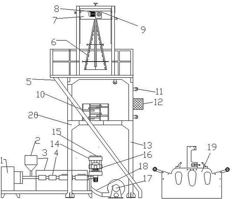
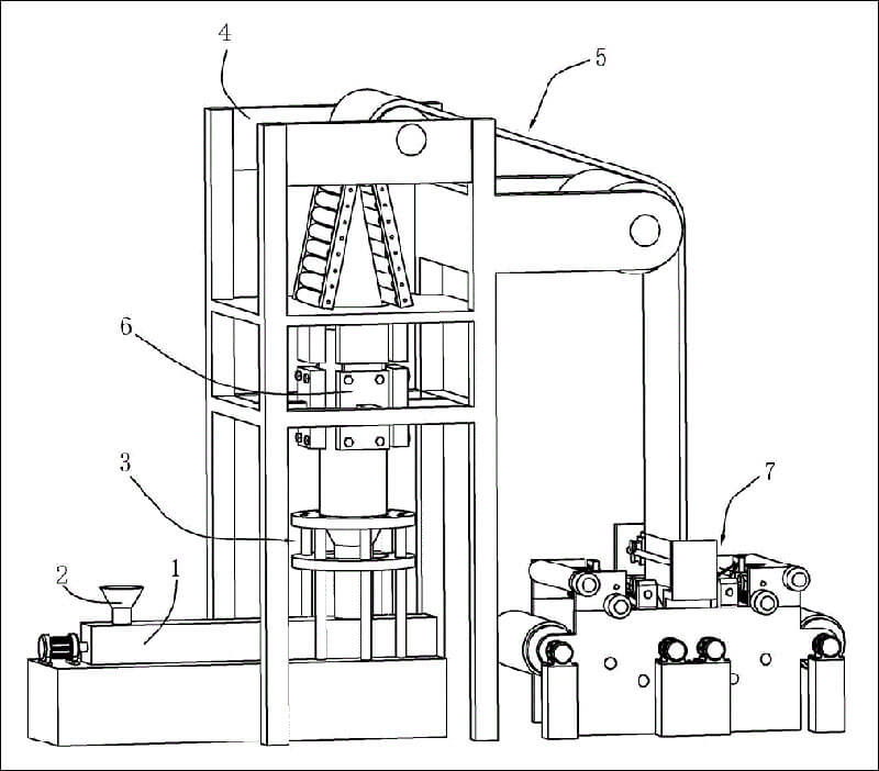
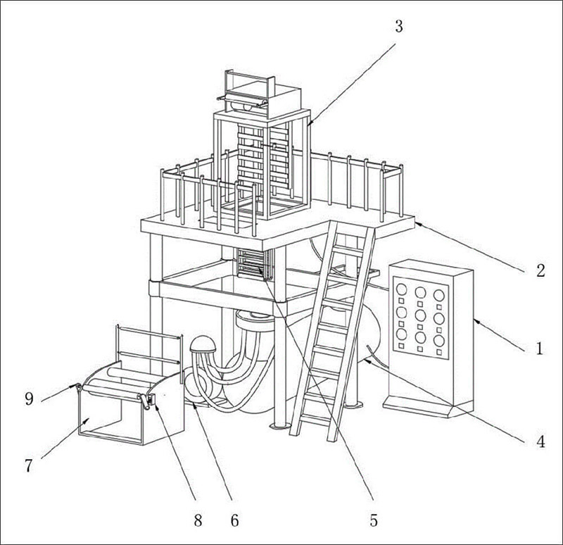
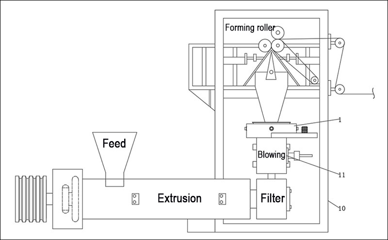
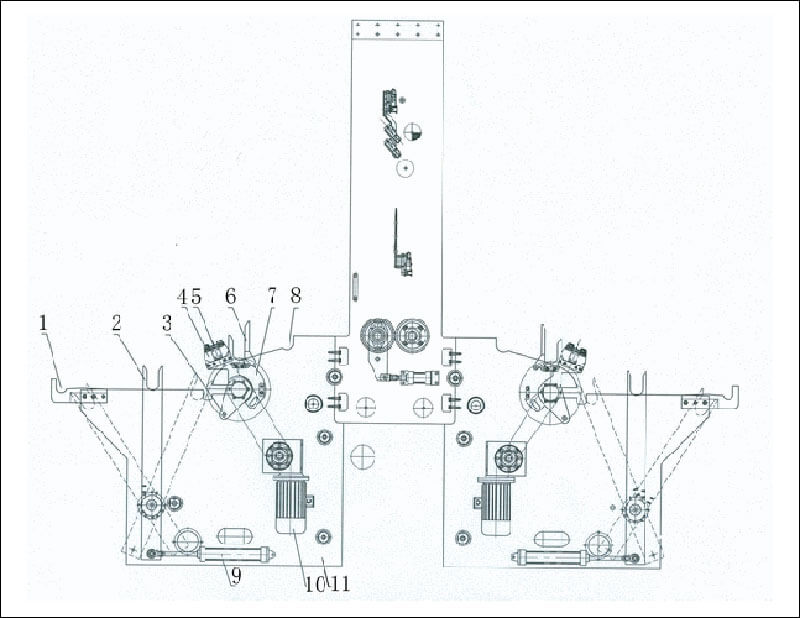
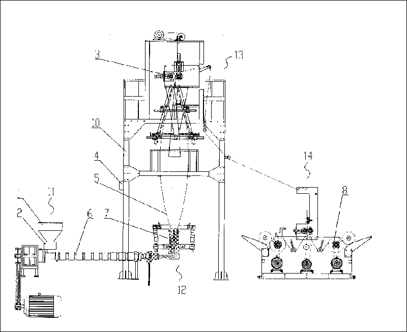
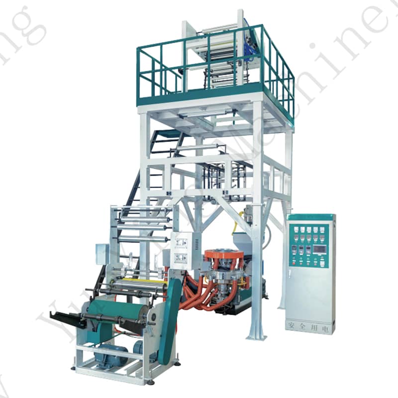
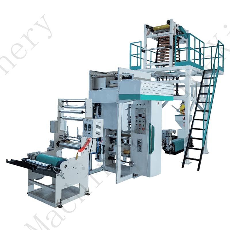
2025-04-09Film blowing machine is a kind of equipment which can heat and melt plastic particle materials to form a melt, and then extrude the melt from the die head by extrusion and make it into a film after inflation and cooling. The film blowing machine is mainly composed of motor, screw and barrel, die head, bubble stabilizer, herringbone plate, traction, winding, etc.
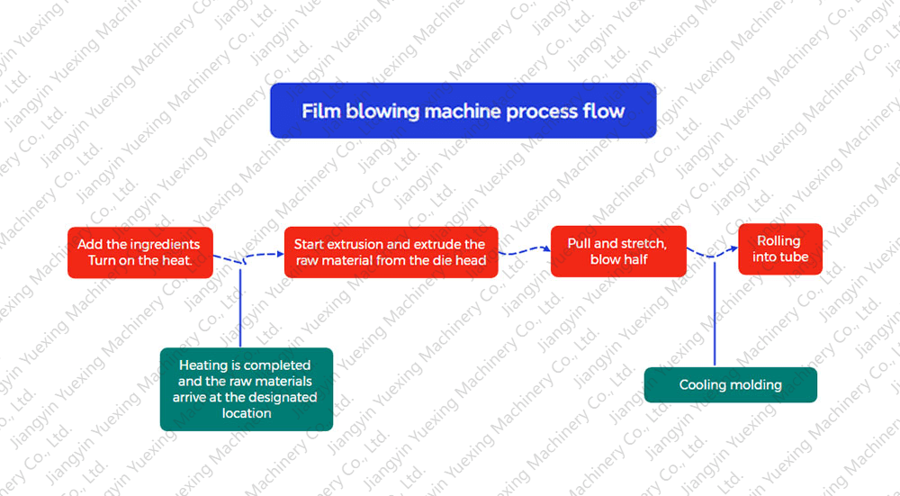
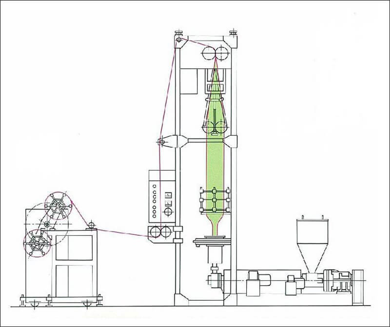
According to the different processing materials, film blowing machines are generally divided into three types: PE, POF and PVC. The films manufactured by film blowing machines are mainly used for high-end packaging applications. The common production process of PE film blowing machines is to first load dry polyethylene (PE for short) granular materials into the hopper. The granules slide from the hopper into the barrel by gravity. After contacting the screw threads in the barrel, the rotating screw uses the vertical thrust of its bevel surface to push the granules forward. During the pushing process, friction will occur between the granules, the screw and the barrel, and there will also be collision and friction between the granules. This kind of friction will generate heat. At the same time, there is also a heater working on the outside of the barrel to provide heat. Under the combined action of internal and external heat, the polyethylene granular materials are melted. The molten material is filtered through the screen changer to remove impurities and flows out of the die head. After cooling, blowing, pulling and winding, it is finally made into a cylindrical finished film.
We have collected 8 working principle diagrams of film blowing machines from the Internet, which you can collect and study.