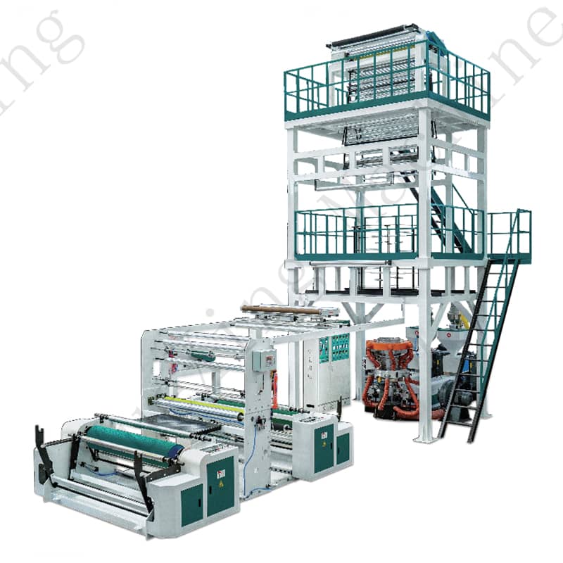
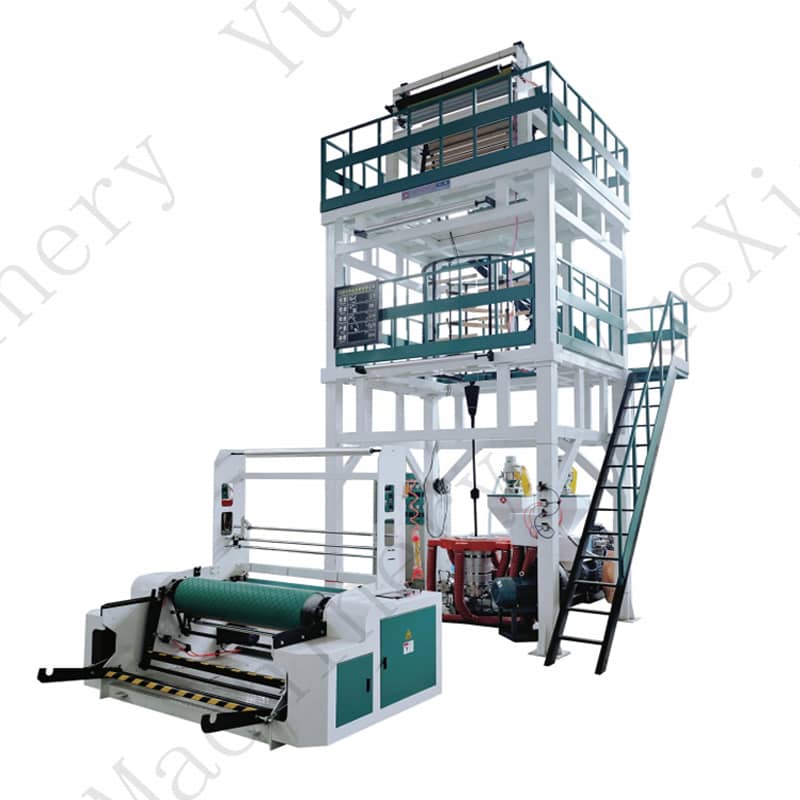
How is Output Capacity (kg/hr) Linked to Maximum Film Width - How Should I Spec the Extruder Size?
2026-04-03In blown film production, output capacity and film width are closely interconnected but governed by two different hardware limits: the extruder screw diameter determines how much melt you can generate, while the die head diameter and blow-up ratio (BUR) dictate the final layflat width.
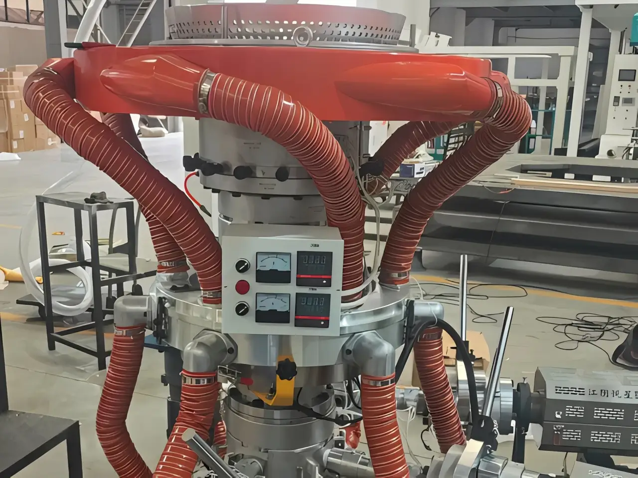
1. Sizing the Extruder by Output Demand
The screw diameter is your primary "engine." As a field-proven benchmark for LDPE:
55mm Screw: Typically delivers 80–120 kg/hr.
65mm Screw: Steps up to 150–200 kg/hr.
90mm Screw: Reaches the high-output bracket of 300–400 kg/hr.
If your production requires high-speed runs or thicker gauges, you must spec a larger screw to ensure the melt pressure remains stable without over-shearing the material.
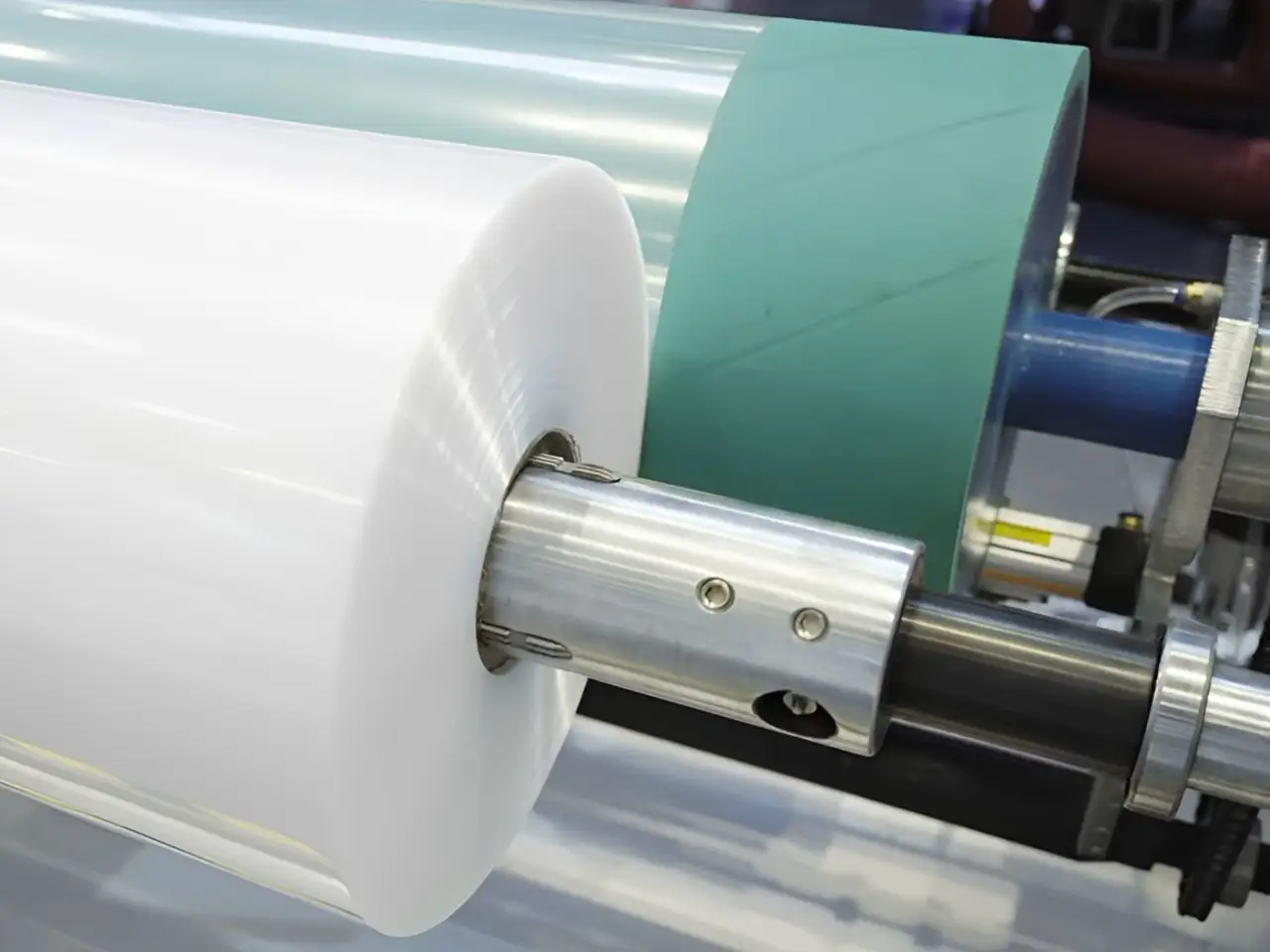
2. Converting Output into Film Width
Once you have the melt, the die head takes over. The relationship is defined by the formula:
Layflat Width = (Die Diameter × π × BUR) / 2
For instance, a 200mm die at a standard 2.5:1 BUR produces approximately 785mm layflat. To scale up to a 1,200mm layflat, you would typically move to a 300mm die (at 2.5:1 BUR). This larger die requires a proportionally higher output rate from the extruder to maintain the internal bubble pressure and cooling efficiency.
3. The "Work Backward" Spec Strategy
To spec the right film blowing machine, don't start with the motor; start with the product. The most reliable engineering sequence is:
Define Target Width & Gauge: What is your widest layflat and thinnest micron requirement?
Calculate Required Output: Based on your desired haul-off speed (m/min) and film dimensions, determine the necessary kg/hr.
Select Hardware: Choose an extruder screw diameter that can comfortably hit that kg/hr at 70-80% load, then pair it with a die head optimized for your BUR range.
This approach ensures you don't end up with an "under-powered" extruder trying to feed a large die, which is the most common cause of bubble instability and gauge variation.
Previous:How to Reduce Energy Consumption in Blown Film Production: 3 Key Strategies to Cut Costs by 30%
Next:How to Calculate Extruder Size and Die Diameter for Blown Film Lines

Since 1999, Yuexing Machinery has been at the forefront of film blowing machine innovation. Our advanced technology and dedication to quality have made us a reliable partner for businesses worldwide. Whether you need single-layer or multi-layer solutions, we are here to meet your needs.